2.3 Installing Optional Service Cards
2.3.1 Location of Optional Service Cards
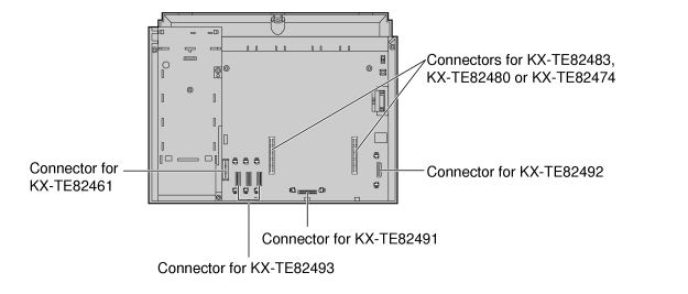
| Optional service cards are installed by opening the front covers of the main unit and affixing the cards to the appropriate connectors. Each card should be installed in the appropriate location as shown below. |
| See "System Components Table" for the description of each optional service card. |
CAUTION
|
To protect the printed circuit boards (P-boards) from static electricity, do not touch parts on the P-boards in the main unit and on the optional service cards. If you must touch the P-boards, wear an earthing strap. |
Note
|
Before installing optional service cards, turn off the PBX and unplug the AC cord. |
2.3.2 3-Port Analogue CO Line and 8-Port Hybrid Extension Card (KX-TE82483)
Function
| Adds 3 outside (CO) lines and 8 hybrid extensions on the KX-TES824 basic system. |
Installing KX-TE82483 to KX-TES824
| 1. |
Loosen the screws and open the top and bottom front covers. (→ 2.2.3 Opening/Closing Covers) |
| 2. |
Using cutting pliers, cut the 6 parts marked with circles, and remove the upper front panel as shown below. |
|
|
| 3. |
Cut off any excess plastic in order to make the surface smooth. |
|
|
| 4. |
Attach the 2 extension connectors to the main unit, install the card as shown below, and secure the 3 extension bolts. |
|
|
| 5. |
Insert the modular plugs of the telephone line cords (2-conductor wiring) into the card's modular CO ports. (→ 2.4.1 Connecting Outside (CO) Lines) |
| 6. |
Connect the line cords to the terminal board or the modular jacks from the telephone company. |
| 7. |
Insert the modular plugs of the telephone line cords (2- or 4-conductor wiring) into the card's modular extension jacks. (→ 2.5.1 Connecting Extensions) |
| 8. |
Wrap the strap around all of the cords. (→ 2.2.4 Securing Cords) |
| 9. |
Close the covers and secure the screws. (→ 2.2.3 Opening/Closing Covers) |
2.3.3 2-Port Analogue CO Line and 8-Port SLT Extension Card (KX-TE82480)
Function
| Adds 2 outside (CO) lines and 8 single line telephone (SLT) extensions on the basic system of KX-TES824/KX-TEM824. |
Installing KX-TE82480 to KX-TES824
Installing KX-TE82480 on 3-Port Analogue CO Line and 8-Port Hybrid Extension Card (KX-TE82483) installed to KX-TES824
Note
|
Install the KX-TE82480 on top of the KX-TE82483. |
| 1. |
Loosen the screws and open the top and bottom front covers. (→ 2.2.3 Opening/Closing Covers) |
| 2. |
Using cutting pliers, cut the 6 parts marked with circles, and remove the lower front panel or both upper and lower front panels as shown below. |
|
|
| 3. |
Cut off any excess plastic in order to make the surface smooth. |
|
|
| 4. |
Attach the extension connectors and extension bolts, install the cards as shown below, and secure the 3 screws. |
|
|
| 5. |
Insert the modular plugs of the telephone line cords (2-conductor wiring) into the card's modular CO ports. (→ 2.4.1 Connecting Outside (CO) Lines) |
| 6. |
Connect the line cords to the terminal board or the modular jacks from the telephone company. |
| 7. |
Insert the modular plugs of the telephone line cords (2- or 4-conductor wiring) into the card's modular extension jacks. (→ 2.5.1 Connecting Extensions) |
| 8. |
Wrap the strap around all of the cords. (→ 2.2.4 Securing Cords) |
| 9. |
Close the covers and secure the screws. (→ 2.2.3 Opening/Closing Covers) |
Installing KX-TE82480 to KX-TEM824
| 1. |
Loosen the screws and open the top and bottom front covers. (→ 2.2.3 Opening/Closing Covers) |
| 2. |
Using cutting pliers, cut the 6 parts marked with circles, and remove the front panel as shown below. |
|
|
| 3. |
Cut off any excess plastic in order to make the surface smooth. |
|
|
| 4. |
Attach the 2 extension connectors to the main unit, install the card as shown below, and secure the 3 screws. |
|
|
| 5. |
Insert the modular plugs of the telephone line cords (2-conductor wiring) into the card's modular CO ports. (→ 2.4.1 Connecting Outside (CO) Lines) |
| 6. |
Connect the line cords to the terminal board or the modular jacks from the telephone company. |
| 7. |
Insert the modular plugs of the telephone line cords (2- or 4-conductor wiring) into the card's modular extension jacks. (→ 2.5.1 Connecting Extensions) |
| 8. |
Wrap the strap around all of the cords. (→ 2.2.4 Securing Cords) |
| 9. |
Close the covers and secure the screws. (→ 2.2.3 Opening/Closing Covers) |
2.3.4 8-Port SLT Extension Card (KX-TE82474)
Function
| Adds 8 single line telephone (SLT) extensions on the basic systems of KX-TES824/KX-TEM824. |
Installing KX-TE82474 to KX-TES824
Installing KX-TE82474 on 3-Port Analogue CO Line and 8-Port Hybrid Extension Card (KX-TE82483) installed to KX-TES824
Note
|
Install the KX-TE82474 on top of the KX-TE82483. |
Installing KX-TE82474 to KX-TEM824
2.3.5 3-Port Caller ID Card (KX-TE82493)
Function
Adds Caller ID support for 3 outside (CO) lines. 1 card can be installed for outside (CO) lines 1–3. A second card can be installed for outside (CO) lines 4–6, and a third card can be installed for outside (CO) lines 7 and 8.
FSK and DTMF Caller ID types are supported. For information on the type of Caller ID used in your area, contact your telephone company. |
| 1. |
Loosen the screws and open the top and bottom front covers. (→ 2.2.3 Opening/Closing Covers) |
| 2. |
Slide the card between the guiderails until it clicks, and attach the connector to it. |
|
|
|
Note
|
Use extra care to make sure you do not damage the part of the case marked with a circle. |
|
| 3. |
Close the covers and secure the screws. (→ 2.2.3 Opening/Closing Covers) |
Note
|
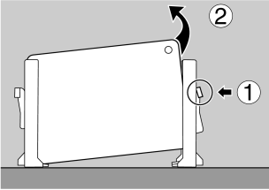
To uninstall the card, follow the instructions illustrated below. |
| 1. |
Push the catch on the side of one guardrail in the direction of the arrow to release it. |
| 2. |
Lift the edge of the card while holding the catch open. (Do not touch the circuit board of the card during the operation.) |
2.3.6 4-Port Doorphone Card (KX-TE82461)
Function
| Supports the connection of 4 doorphones and 4 door openers. |
| 1. |
Loosen the screws and open the top and bottom front covers. (→ 2.2.3 Opening/Closing Covers) |
| 2. |
Attach the 4-Port Doorphone Card to the main unit, connect the cord to the Doorphone Card Connector and secure the screw. |
|
|
|
Note
|
Use extra care to make sure you do not damage the part of the case marked with a circle. |
|
| 3. |
Close the covers and secure the screws. (→ 2.2.3 Opening/Closing Covers) |
2.3.7 Message Expansion Card for DISA/UCD OGMs (KX-TE82491)
Function
| When an optional message expansion card for DISA/UCD OGMs is added, up to 2 messages can be played simultaneously for callers and the total recording time of the PBX is increased from 3 to 6 minutes. |
| 1. |
Loosen the screws and open the top and bottom front covers. (→ 2.2.3 Opening/Closing Covers) |
| 2. |
Slide the card between the guiderails until it clicks, and attach the connector to it. |
|
|
|
Note
|
Use extra care to make sure you do not damage the part of the case marked with a circle. |
|
| 3. |
Close the covers and secure the screws. (→ 2.2.3 Opening/Closing Covers) |
Note
|
To uninstall the card, follow the instructions illustrated below. |
| 1. |
Push the catch on the side of one guardrail in the direction of the arrow to release it. |
| 2. |
Lift the edge of the card while holding the catch open. (Do not touch the circuit board of the card during the operation.) |
2.3.8 2-Channel Voice Message Card (KX-TE82492)
Function
| Provides 60 minutes of recording time (2 channels) for messages using the Built-in Voice Message Feature. |
| 1. |
Loosen the screws and open the top and bottom front covers. (→ 2.2.3 Opening/Closing Covers) |
| 2. |
Slide the card between the guiderails until it clicks, and attach the connector to it. |
|
|
|
Note
|
Use extra care to make sure you do not damage the part of the case marked with a circle. |
|
| 3. |
Close the covers and secure the screws. (→ 2.2.3 Opening/Closing Covers) |
Note
|
To uninstall the card, follow the instructions illustrated below. |
| 1. |
Push the catch on the side of one guardrail in the direction of the arrow to release it. |
| 2. |
Lift the edge of the card while holding the catch open. (Do not touch the circuit board of the card during the operation.) |


