2.2 Installing the Advanced Hybrid System
2.2.1 Unpacking
| The following items are included upon shipment. |
|
|
|
The type of the AC cord may vary depending on the country/area of use.
More than one type of AC cord may be included for countries/areas in Central and South America. |
|
2.2.2 Names and Locations
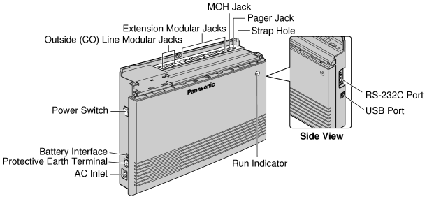
2.2.3 Opening/Closing Covers
Opening Covers
| 1. |
Loosen the top cover screw. |
| 2. |
Remove the top front cover. |
|
|
|
Note
|
The screw cannot be removed from the cover. |
|
| 3. |
Remove the 2 bottom-cover screws. |
|
|
| 4. |
Open the bottom front cover. |
|
|
Closing Covers
| 1. |
Replace the bottom front cover. |
|
|
| 2. |
Attach the 2 bottom-cover screws. |
|
|
| 3. |
Replace the top front cover and tighten the screw. |
|
|
Note
|
For safety reasons, keep the front covers closed while the PBX is in operation. |
CAUTION
|
Tighten the above screw firmly to prevent the main unit from falling when the PBX is carried. |
2.2.4 Securing Cords
| 1. |
Insert the rivet into the hole in the strap. |
| 2. |
Insert the rivet and strap into the hole on the PBX. |
|
|
| 3. |
Wrap the strap around all of the cords. |
|
|
| 4. |
Close the covers. (→ 2.2.3 Opening/Closing Covers) |
| 5. |
Tie together all of the connected cords and secure them to the wall so that they cannot be pulled out of the PBX. |
|
|
Note
|
To remove the rivet, use a screwdriver as shown below. |
2.2.5 Connecting Frame Earth
IMPORTANT
|
Connect the frame of the PBX to earth. |
| 1. |
Loosen the screw. |
| 2. |
Insert an earthing wire (user-supplied)*. |
| 3. |
Tighten the screw. |
| 4. |
Connect the earthing wire to earth. |
|
|
|
|
| Use an earthing wire that has a conductor with a cross-sectional area of at least 0.75 mm2 or 18 AWG. Green-and-yellow insulation is required. |
|
| • |
Be sure to comply with all applicable laws, regulations, and guidelines. |
| • |
Proper earthing is very important to protect the PBX from external noise and to reduce the risk of electrocution in the event of a lightning strike. |
| • |
The AC cable's earthing pin may not be enough to protect the PBX from external noise and lightning strikes. A permanent connection must be made between earth and the earth terminal of the main unit. |
2.2.6 Connecting Backup Batteries
| Backup batteries and a backup battery cable (KX-A227) provide a backup power supply to allow full use of the PBX in the event of a power failure. In a power failure, the backup batteries automatically maintain the power for the PBX without interruption. |
| 1. |
Set the Power Switch of the PBX to the "OFF" position and disconnect the AC cord from the AC outlet. |
| 2. |
Connect the backup battery cable with 2 identical VRLA (Valve Regulated Lead Acid) batteries (12 V DC × 2). |
|
|
| • |
Turn on the power switch of the PBX only after the installation of the PBX is finished and AC cord is plugged into the AC outlet. |
| • |
For each backup battery, battery capacity of 14 Ah or below is recommended (otherwise, the battery charge may not be maintained). |
| • |
Make sure that the type and capacity of the 2 backup batteries are identical. |
| • |
The backup battery cable should not be exposed to direct sunlight. Keep the backup battery cable and the backup batteries away from heating appliances and fire. Place the backup batteries in ventilated place. |
| • |
For details about the backup batteries, refer to the manual intended for the batteries. |
CAUTION
|
• |
Be sure to comply with all applicable laws, regulations, and guidelines. |
|
• |
Make sure that the polarities of the backup batteries and wiring are correct. |
|
• |
Make sure that you do not short the backup batteries or cables. |
|
• |
When replacing one of the batteries, use only the same or equivalent battery type recommended by the battery manufacturer. There is a danger of explosion if the backup batteries are incorrectly replaced.
Dispose of used batteries according to the manufacturer's instructions. |
|
• |
The charging time of your battery varies depending on the charge remaining, the characteristics of the battery charger, and the ambient temperature.
Refer to the instructions provided by the battery manufacturer for details.
The following is an example calculation of the time needed to charge a drained battery (Battery rating: 24 Ah) connected to the PBX: |
2.2.7 Wall Mounting
| The PBX is designed for wall mounting only. The wall where the PBX is to be mounted must be able to support the weight of the PBX. When wall mounting the main unit, use either the included screws, or screws of the same size. |
Mounting on a Wooden Wall
| The included screws may be used when mounting the main unit on a wooden wall. |
| 1. |
Place the template (found on the last page of this manual) on the wall to mark the 3 screw positions. |
|
|
|
Note
|
When you print out the template, the distance on the paper output may deviate slightly from the indicated measurement. In this case, use the indicated measurement. |
|
| 2. |
Fit the washers on the screws, and drive the screws into the wall. |
|
|
| 3. |
Affix the PBX to the screw heads. |
|
|
Notes
|
• |
Do not block the openings of the cabinet. Leave at least 20 cm of space above and 10 cm to the sides of the PBX for ventilation. |
|
• |
Make sure that the wall behind the cabinet is flat and free of obstacles, so that the openings on the back of the cabinet will not be blocked. |
|
• |
Be careful not to drop the cabinet. |
Mounting on a Concrete or Mortar Wall
| The included screws may be used when mounting the main unit on a concrete or mortar wall. User-supplied anchor plugs are also necessary. |
| 1. |
Place the template (found on the last page of this manual) on the wall to mark the 3 screw positions. |
|
|
|
Note
|
When you print out the template, the distance on the paper output may deviate slightly from the indicated measurement. In this case, use the indicated measurement. |
|
| 2. |
Drill holes in the wall as marked and fit the anchor plugs (not included) into the holes. |
|
|
| 3. |
Fit the washers on the screws, and drive the screws into the anchor plugs. |
|
|
| 4. |
Affix the PBX to the screw heads. |
|
|
Notes
|
• |
Do not block the openings of the cabinet. Leave at least 20 cm of space above and 10 cm to the sides of the PBX for ventilation. |
|
• |
Make sure that the wall behind the cabinet is flat and free of obstacles, so that the openings on the back of the cabinet will not be blocked. |
|
• |
Be careful not to drop the cabinet. |
2.2.8 Installing Surge Protector
Overview
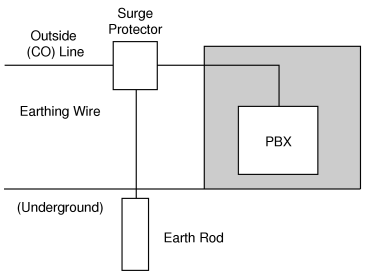
| A massive electrical surge can be caused if lightning strikes a telephone cable 10 m above ground, or if a telephone line comes into contact with a power line. A surge protector is a device that is connected to an outside (CO) line to prevent potentially dangerous electrical surges from entering the building via the outside (CO) lines and damaging the PBX and connected equipment. |
To protect the PBX from electrical surges, we strongly recommend connecting the PBX to a surge protector that meets the following specifications: |
| – |
Surge arrestor type: 3-electrode arrestor |
| – |
DC spark-over voltage: 230 V |
| – |
Maximum peak current: at least 10 kA |
| Additionally, proper earthing is very important for the protection of the PBX. (→ 2.2.5 Connecting Frame Earth) |
Many countries/areas have regulations requiring surge protection. Be sure to comply with all applicable laws, regulations, and guidelines. |
Outside Installation
|
|
| If you install an extension outside of the building, the following precautions are recommended: |
| a. |
Install the extension wire underground. |
| b. |
Use a conduit to protect the wire. |
|
Note
|
The surge protector for an extension is different from that for an outside (CO) line. |
|
|
Installation of an Earth Rod
| 1. |
Connect the earth rod to the surge protector using an earthing wire with a cross-sectional area of at least 1.3 mm2. |
| 2. |
Bury the earth rod near the protector. The earthing wire should be as short as possible. |
| 3. |
The earthing wire should run straight to the earth rod. Do not run the wire around other objects. |
| 4. |
Bury the earth rod at least 50 cm underground. |
|
Notes
|
• |
The above figures are recommendations only. |
|
• |
The length of the earth rod and the required depth depend on the composition of the soil. |
|


